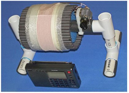
Introduction Graham Maynard’s introduction of an innovative ferrite sleeve antenna early last year kicked off a torrent of experimentation in the Ultralight radio group, as experimenters quickly discovered the performance potential of the new design. Monster-sized loops (and multiple design controversies) seemed to be the order of the day at first, as curious DXers of modest means and limited technical ability probably wondered whether the FSL antenna breakthrough would ever make any difference to them personally.
The FSL antennas are still expensive and somewhat tricky to construct, but after the design and construction (and donation) of several smaller-sized models, they are no longer extremely rare. Quite a few DXers can now enjoy the breakthrough performance offered by these new antennas—if they can learn a few operating tricks to maximize their performance.
There is a definite learning curve involved in mastering these antennas, and no DXer should expect to become an expert overnight. Although the basic function of the FSL antenna is similar to that of an air core box loop, both the tuning sharpness and the inductive coupling distance (to the radio) are far more important for DXing success. FSL skill requires some serious practice. Attempting to use an FSL antenna like an air core box loop will never provide optimal results—and may even lead a puzzled DXer to wonder if the antenna is working at all (as even I wondered, after building my first FSL antenna model
 FSL Antenna Advantages—and Disadvantages Essentially, the innovative antennas provide DXers with an all-new operating option—very high gain, low-noise reception in an extremely compact package. This new option comes with the side effects of serious cost and weight, however. The overall DXing value of an FSL antenna increases dramatically in extremely tight spaces such as ocean side cliffs, where other high gain antenna options are ruled out because of inadequate setup space. In these special environments the FSL antennas have already demonstrated superior transoceanic performance during both Ultralight radio and Perseus-SDR DXpeditions (in a new Broadband FSL form). The FSL’s also excel at providing lower noise reception than much larger air core loops.
But such DXing performance comes with a price—both in component cost and antenna weight. Although several construction articles have been published, FSL antennas are still not commonly available. The cost of construction for competitive models can run well into hundreds of dollars, and although the FSL’s will perform very well in back yards, open spaces and public parks, much cheaper air-core loop options are available for such wide open environments. Assuming that adequate real estate is available, obtaining high gain from cheap wire is usually preferable to obtaining it from costly ferrite.
Although indoor shacks are not ideal DXing environments for either FSL or air core loop antennas, the FSL’s unique ability to deliver high gain reception from an extremely compact size can make these new antennas an attractive option for those indoor DXers without the space for 4 foot (or larger) box loops. The value tradeoff between the FSL’s and air core loops is certainly an interesting one-- and each individual DXer must evaluate whether the FSL’s unique advantages justify its higher construction cost.
 Performance Basics After four major ocean coast DXpeditions and two Fall DX Seasons, the author has learned a few tricks on squeezing the best possible performance out of these new antennas. There are certain factors which will contribute to your success as an FSL antenna user, regardless of your model’s size, shape or design. If at all possible, try to follow these basic ground rules:
1) Use the antenna away from any RF noise sources, and if possible, away from indoor house wiring. Best FSL antenna results usually are obtained outdoors, where the antenna’s low-noise reception and sharp nulling capabilities can be fully appreciated. The antennas can still provide satisfactory DXing results indoors, but with some reduction in their overall capability related to the degree of RF noise and AC wiring runs existing in these environments.
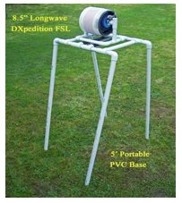
2) Place the FSL antenna in an elevated position (above ground level) on a non-conducting surface like a wooden table, or a stone fence. Ideal results can be obtained by placing the FSL on an insulating surface (like a custom PVC base) at least four feet high (see photo at left). This provides excellent DXpedition performance.
3) The FSL antennas cannot operate in the rain without some type of waterproofing system (a simple sheet of rubber, plastic rain hood or plastic tote enclosure). Without such protection the rain will interfere with the variable cap’s operation, making tuning impossible (although rain will not permanently damage the antenna).
4) The variable capacitor in an FSL antenna tunes VERY sharply, especially on the high band frequencies. A vernier-drive variable capacitor helps greatly during this critical tuning process, along with a large-diameter tuning knob. Because of the extremely high-Q tuning system an FSL’s tuning adjustment is razor-sharp, providing some attenuation of stations even 1 kHz away from its selected frequency. Although this high-Q tuning system can assist in reducing splatter from off-frequency pest stations, it also makes it more important to tune the antenna carefully for best results.
5) It is possible to tune an FSL antenna simply by listening for a weak station’s audio signal boost when the antenna’s frequency matches that of an inductively coupled portable radio, but depending on the portable radio model, this process may be tricky. The analog models usually couple up very well in this process, but digital models like the Tecsun DSP Ultralights (which have a delayed audio response as the Si4734 chip processes frequency changes) are among the trickiest. In such a situation, repeated practice is helpful, as well as the use of another portable with LED tuning lights (Sony ICF-2010, etc.) for the express purpose of tuning the FSL quickly to the desired frequency. After repeated practice, a skillful operator can tune an FSL simply by listening for the signal boost on a weak station-- even on the Tecsun DSP Ultralights.
 6) The optimal inductive coupling distance between a portable radio and the FSL’s sleeve coil is another razor-sharp adjustment, which should be practiced at first for best results, and also whenever a different portable radio is used with the FSL antenna.
7) FSL antennas can not only provide an inductively coupled boost when the portable radio is placed a few inches in front of the sleeve coil, but can also provide an equal or stronger DXing boost when the radio is placed a few inches to the left or right of the sleeve coil-- if the radio’s loopstick is directly lined up with one of the ferrite rods (or bars) in the FSL. Both methods should be tried when a DX station is extremely weak, since either method may provide a superior signal boost. The FSL side coupling method usually provides better results with ferrite rod FSL’s, as opposed to ferrite bar FSL’s.
8) Matched-size plastic totes are extremely useful for carrying an FSL antenna outside the house, and can frequently double as a weatherproof DXing enclosure for the antenna and inductively coupled radio. All of the FSL models designed by the author have a matched-size plastic tote, which is commonly available at major stores. When filled with padding material such as pipe insulation, these totes can protect the FSL during shipping across the country-- and can also help it survive an unplanned “drop test” during DXpeditions. With Murphy’s Law in mind, remember that plastic totes and padding material are dirt cheap—much cheaper than buying replacement ferrite rods.
9) One of the major advantages of FSL antennas (over air core loops) is lower noise pickup, especially when signals are very weak. If you have an RF noise source, rotating the FSL antenna to null the noise source is usually possible, and can even lead you to the direct source of the noise if you check the null bearings on the FSL at different locations.
10) The quality and depth of a signal null available on an FSL antenna is directly related to the quality of the RF environment in which it is used. For best results all stray conductors (house wiring, metal tables, aluminum gutters, etc.) should be removed far from the FSL antenna operating area. The quality of a signal null is also related to the FSL’s design (i.e. the symmetry of its cylindrical ferrite sleeve, and the degree to which the variable cap size and variable cap wiring cause distortions in the symmetrical RF reception pattern). For the best possible pest station nulls, the use of a rotating support structure (i.e. Lazy Susan table) is recommended.
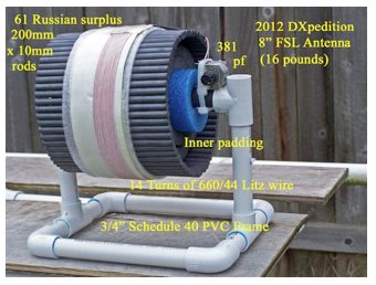 11) The most sensitive FSL models tend to be quite heavy, and require sturdy support structures during both DXpeditions and household usage. Almost all of the FSL’s heavy weight comes from the multiple ferrite rods. Although all DXers dream of maximum weak-signal gain, set a reasonable FSL weight limit when planning a DXpedition involving dark ocean beaches, or unfamiliar ocean side cliffs. The weight of the 2012 “DXpedition” model (at left) was purposely limited to 16 pounds (7.3 kg) for antenna and operator survival at these risky venues.
12) FSL antennas are sinister-looking creations which resemble rings of dynamite, submachine gun magazines or Gatling Guns. They tend to raise the curiosity and anxiety level of strangers—particularly airport TSA agents. When planning a major DXpedition serious consideration should be given to shipping these FSL antennas through the mail in advance, directly to the motel near the DXpedition site. On the other hand, the subversive-looking nature of the antennas may work to the owner’s advantage in keeping curious onlookers a safe distance away from his DXing site—especially when he is likely to be the only reasonably normal individual on an ocean side cliff around 0300 local time.
Step-by-Step Operating Instructions Before using your FSL antenna for DXing, ensure that the antenna is placed on a non-conducting surface in an elevated position, and as far away as possible from RF noise sources and stray conductors (house wiring, aluminum gutters, etc.). Ensure that the FSL antenna’s ferrite rods are broadside to the desired DX direction (i.e. the antenna’s null position is when the ferrite rod edges are pointing directly toward a station). If you are DXing outdoors and a possibility of rain exists, make sure that you are prepared with some type of FSL waterproofing system (plastic tote, plastic rain hood or rubber cover).
1) Tune in the desired weak station’s frequency on any portable radio with a loopstick (i.e. not the Eton E1, or other such models with no loopstick). Best FSL antenna results are obtained when the DX station is extremely weak, or even inaudible on the portable radio.
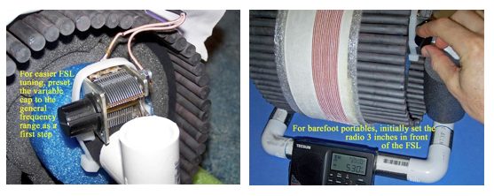
2) For a “barefoot” portable radio (without any transplanted loopstick), initially place the portable radio so that the radio’s loopstick is about 3” (75 mm) in front of the FSL coil (see photo above right). For radios with a transplanted 7.5” loopstick, initially place the radio about 7” (18 cm) in front of the FSL coil.
3) Prior to tuning the FSL’s variable capacitor to provide an FSL signal boost to the portable radio, check to ensure that the FSL’s variable cap is set at a position fairly close to the frequency of the portable radio (see photo above left). The variable cap’s tuning plates can be observed to preset this approximate frequency (i.e. fully meshed for a very low band signal, half open for a mid-band signal, and close to fully open for a high-band signal), thereby saving time and effort in the next step.
 4) VERY SLOWLY tune the FSL’s variable cap until a POWERFUL signal boost is heard on the portable radio’s tuned frequency. When this variable cap position is found, continue to SLOWLY adjust the variable cap in MINUTE movements around this position until optimal weak signal audio is received on the portable radio. This step tends to be easier on the portables without the Si4734 DSP chip (i.e. a little trickier on the Tecsun DSP Ultralights), but can be performed well on all portables with a little practice. If the portable radio is tuned to a frequency without any weak station, the FSL antenna will simply boost the background noise on the frequency (although the antenna will be set up for reception of any weak station that may fade in on the frequency).
NOTE: For DXpeditions and other situations where extremely rapid and accurate FSL tuning is essential, an alternative system of quickly tuning the FSL with an SSB spotting receiver’s LED signal display is recommended (see photo at right). This system can accurately tune in any FSL frequency within a couple of seconds. Details are provided in the “4A” step below.
4A) Using an SSB spotting receiver such as the Sony ICF-2010, check the strength of DX station carriers of interest using the receiver’s pre-stored memory presets. When a desired DX station’s SSB carrier is showing some strength and a gain boost from the FSL antenna is desired, place the SSB spotting receiver about 3” (75 mm) in front of the FSL coil. While observing the receiver’s LED signal display, slowly tune the FSL’s variable capacitor until the maximum number of signal LED’s lights up on the SSB spotting receiver. The FSL antenna is now accurately tuned to provide a gain boost to either the SSB spotting receiver, or to any other portable radio tuned to the DX station’s frequency (i.e. Ultralight radio, if desired).
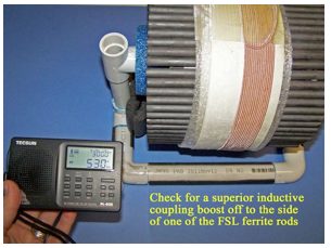 5) Once the FSL antenna’s variable cap has been accurately tuned to provide its strongest inductive coupling boost to the radio, SLOWLY vary the portable’s distance from the FSL coil to check if an even greater gain boost is available a few inches further from (or closer to) the coil. Because of the FSL’s high-Q system this is another sharp adjustment, which will provide the antenna’s best possible DXing gain boost when optimized. This optimal inductive coupling distance may vary with different portable radios, and changes in the tuned frequency.
6) An FSL antenna can occasionally provide a superior inductive coupling boost when the radio is held a few inches off to the side of the ferrite sleeve, as opposed to a few inches in front of the sleeve. This option works best on ferrite rod FSL models (as opposed to ferrite bar models). As an optional step, to check if this superior inductive coupling boost is available, hold the radio initially about 3” (75 mm) off to the side of one of the ferrite rods, so that the radio’s internal loopstick is lined up with the ferrite rod. Then vary the inductive coupling distance a few inches to the left or right, to maximize the inductive coupling boost. If such a method provides a superior DXing boost, proceed to Step # 7—otherwise, simply return the radio to the optimal inductive coupling position determined in Step #5 above (in front of the FSL coil).
7) Once the antenna’s variable cap and inductive coupling distance have both been optimized as described above, the FSL is prepared to provide its highest gain DXing boost on the frequency of choice. Ensure that these adjustments remain constant during any MP3 recording sessions (if desired).
 8) To obtain the best FSL null on a pest station, first remove your portable radio from the FSL’s inductive coupling area, and rotate the radio to find an accurate null bearing on the pest. If necessary, detune the pest station a few kHz until an accurate null bearing can be determined. Once this is found, place your portable radio down on a flat surface at this exact bearing (while it is nulling the pest station). Rotate the FSL antenna so that the ferrite rods (or bars) are all parallel to the portable radio’s internal loopstick (usually, this direction is also parallel to the portable radio’s front cabinet face). A “Lazy Susan” support table is very helpful in this process. Depending upon the various factors described in the “Performance Basics” Step #10 above, this signal null may be either very deep, or very shallow. Best nulling results are obtained in outdoor environments, and when the FSL antenna’s design minimizes disruptions to its reception pattern (by having both an extremely symmetrical ferrite sleeve, and the shortest possible wiring detours to a small-sized variable cap).
Summary The new FSL antennas have the potential to completely transform your hobby experience-- particularly the thrill of chasing weak-signal DX in extremely narrow sites. The high-Q tuning system is unlike that of any other antenna, but the DXing performance advantage for those who can master it is also unprecedented. Whether your intention is to use the new antenna in a small indoor shack or at an extremely narrow ocean side cliff, the FSL will deliver astonishing weak-signal gain for its size—once you master its operation. The author sincerely hopes that this article will enable you to develop such FSL- DXing mastery-- and the unprecedented hobby satisfaction that will result from it!
73 and Good DX,
Gary DeBock (in Puyallup, WA, USA)
 Addendum- The New Broadband FSL Antenna The Broadband FSL concept was the brainchild of Chuck Hutton, who believed that the antenna’s single-optimized frequency design could be modified to allow Perseus-SDR DXers to enjoy the same ocean side cliff DXing that had proven so effective with Ultralight radios (with the additional benefit of spectrum capture). Chuck ‘s interest and involvement was essential to the project, which gained momentum after two successful Ultralight DU-DXpeditions to the Oregon cliffs this summer.
After my August 2012 DXpedition to the “Rockwork 4” cliff south of Cannon Beach, both Chuck and hometown buddy Guy Atkins developed versions of a Broadband FSL by removing the variable capacitor, and adding a high-gain amplifier between the FSL and Perseus-SDR to provide additional performance. Guy’s version used the Wellbrook FLG100LN amplifier as an interface between a 7” FSL and his Perseus, and he reported excellent TP-DXing results with this configuration during a DXpedition trip to Oregon’s Cape Perpetua in September. Guy’s 7” Broadband FSL configuration was duplicated by Victoria DXer Walt Salmaniw during a DXpedition trip to Oregon’s “Rockwork” cliff (south of Cannon Beach) in October , who also reported excellent TP-DXing results with his Perseus.
Guy’s own description of his Broadband FSL system is pasted below, along with two photos showing the antenna’s appearance (at right) and car roof-top setup arrangement (on the next page). The supreme attraction of this antenna is that a DXer can simply drive up to one of the cliff-side DXing sites and record spectrum on his Perseus SDR—without the need to set up any PVC poles, wires, or any other antenna components. It’s enough to make even an Ultralight radio DXer envious!
From Guy Atkins (used with permission): With Gary's encouragement and supply of a regular tuned FSL, and Chuck Hutton's help with electrical formulas and initial impedance measurements, I was able to convert the FSL into a broadband (non-tuned) loop for capturing the entire band with Perseus SDR recordings. The antenna accompanied me to Oregon, secured inside a container strapped to the roof of our family's vacation vehicle. The 7-inch FSL was converted to broadband use by the removal of the tuning capacitor and the addition of a Wellbrook FLG100LN amplified Flag antenna module.
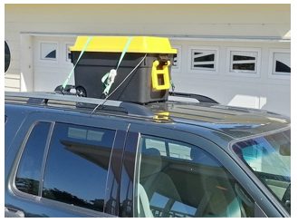 A photo of the modification is attached, along with a picture of the transport container.
Tests at home showed that the antenna works perfectly well inside the box on the roof of the SUV... there's no need to brave the wind, cold, and possible rain outside on the side of the cliff!
I did all my DXing from the comfort of the driver's seat, with the computer and Perseus receiver on the center console. I felt a bit guilty to be enjoying such comfort, knowing that Gary had braved the cold, damp, and darkness at this very same spot!
Thanks for blazing the cliff DXing trail, Gary :^)
While still in Puyallup I was able to verify that the broadband FSL picks up TP carriers (738 Tahiti) equally well as a full size Wellbrook K9AY antenna. Based on this result I was fairly sure that the antenna would work well in an actual DXpedition situation.
